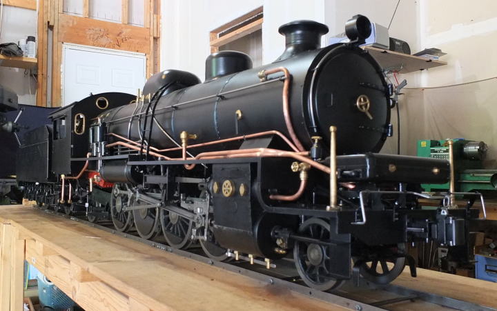
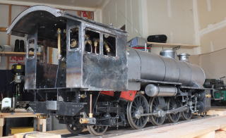
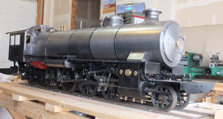
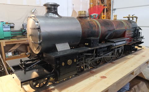
Description of 5 inch Live Steam Locomotive D50 725 of Japan National Railway
<Presented by Hideoki Kimura from July 2006 in JAPAN and USA>
This engine has been completed except for number plates in 14 years. It
has moved to Muroran, Kamaishi, Kimitsu in Japan and Indiana in the U.S.
I made all parts from steel bars, plates, pipes and cast irons. Some parts
such as a boiler are made of brass and copper.
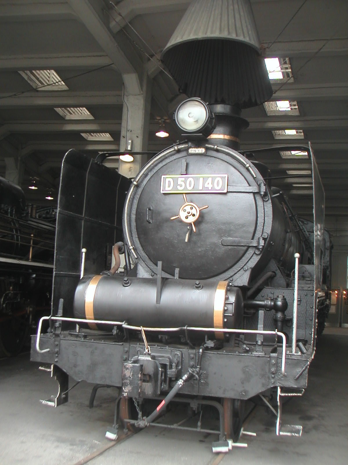
Type of D50 Engine in Japan National Railway. Only tow of 380 engines made in Japan are stored now.
In Umekoji Steam Locomotive Museum(July 2006)
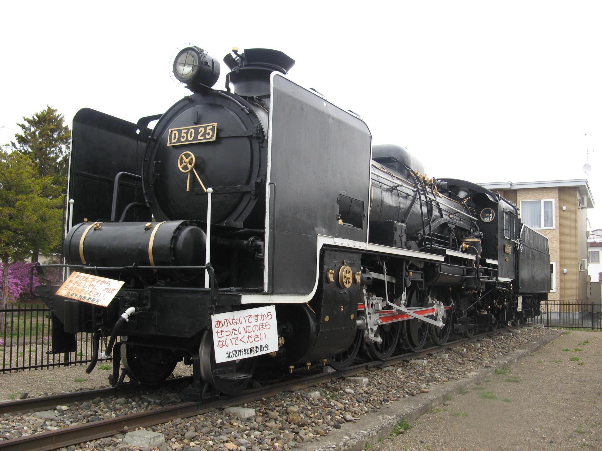
Sanji Park in Kitami City (29 Apr. 2008)
Dates
Titles
Topics
Photos
Total Hours
3
Sep 2020
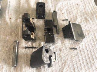
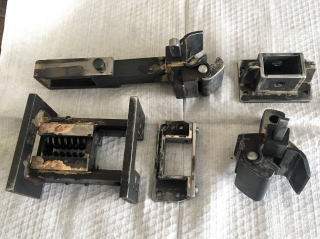
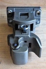
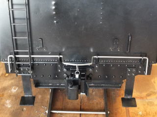
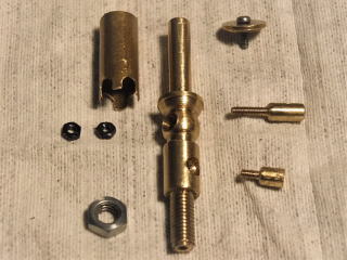
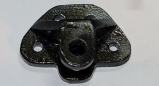
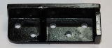
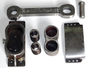
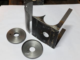
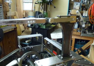
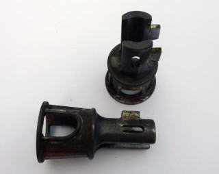
Coupler
Couplers were the last parts I made. It was difficult to make due to the
complex shape. They were made by brazing several parts. The parts I got
from my friend (right side photo) was very useful to design it.
5,888
7
May 2020
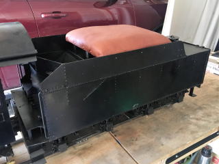
Seat
My first skin work! A driver's seat was made of deer skin with woods and
cusions.
5,838
12
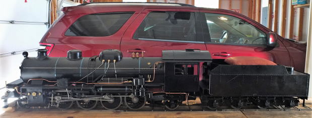
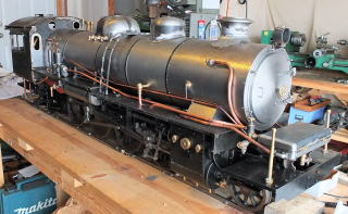
Apr. 2020
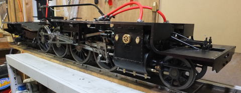
Painting
COVID-19 came suddenly. I stayed at home to work. I got an enough time
for D50. I used it to paint D50 body. Every part of the body was disassmbled
and painted.
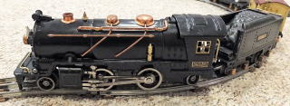
I remained pipes and parts made by brass without paints. It is looked
like prewar Lionel models I like. Lionel 262E
5,824
26
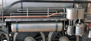
Feb. 2020
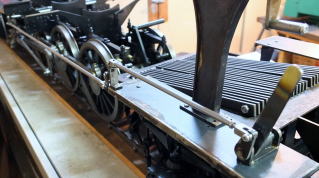
Compressed Air Cooling Pipes
They are made of 4 mm steel bars. they look good.
5,729
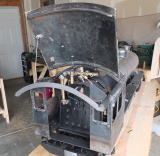
19
Jan. 2020
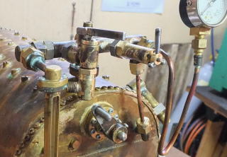
Plumbing
These pipes are all dummies made of copper pipes of 5mm and 8mm in diameter.
5,714
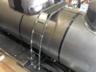
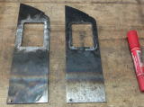
22
Sep. 2019
Ladder
This shape is easy to make, but I needed some hours to cut plates.
I spent a lot of time to visit railroad spots and purchase train models
this summer.
5,668
6
May 2019
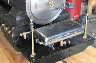
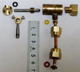
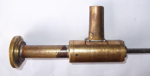
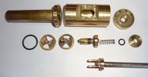
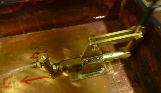
Water Heater
This water pump is not a general round type of Japan National Railway.
I made an original restangle type.
5,605
3
Mar. 2019
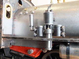
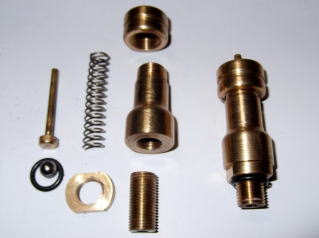
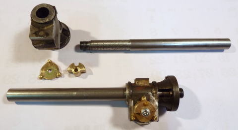
Feed Water Pump
This feed water pump is not a general type of Japan National Railway.
It is an old original type. Becuase I don't know its exact shape, I imaged
it to design. This shape might be different.
I didn't have enough time to make it at my garage. This winter was very
cold in Indiana.
5,540
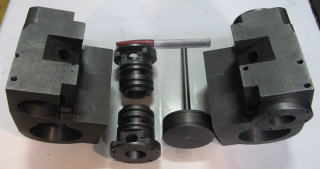
11
Oct. 2018
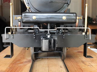
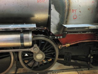
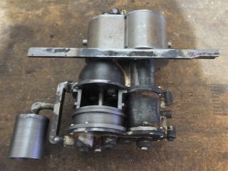
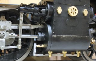
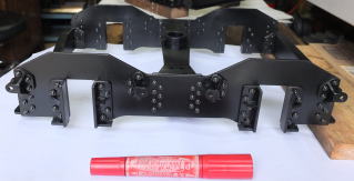
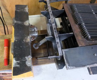
Compressor
It took three months to make a dummy compressor which had complex shape.
It fixed by a bar between front and rear running boards. The compressor has a hole at the back side, because the brake bar (only
model) interferes with it.
5,466
23
Jun. 2018
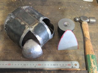
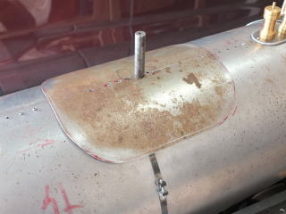
Sand Dome
It was very difficult to make round parts on the corner. I made them finally
by hammering sheets on a dent block, after I failed three times. The sand
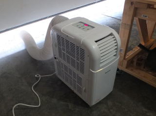
dome was soldered by silver from 12 parts. It took 44 hours. A portable air conditioner I bought is very
useful for too hot garage in Indiana
5,351
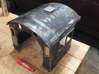
15
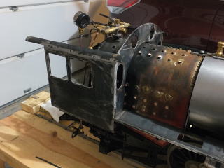
Apr. 2018
Cab
The cab was completed in nine month after begining. The roof can be opened
for driving. Designed hinge mechanism has good performance. The removal
roof has suitable shape without big distortion made by solder burner.Rear
walls can be removed by screws in order to drive the engine.
Name plates and number plates will be attached finally.
5,297
10
Jan. 2018
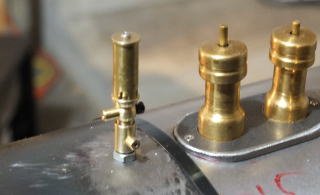
Whistle(Dummy)
The whistle made by scale of 1/8.4 becomes delicate form. It may be broken
by hitting in the future.
5,217
22
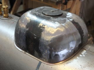
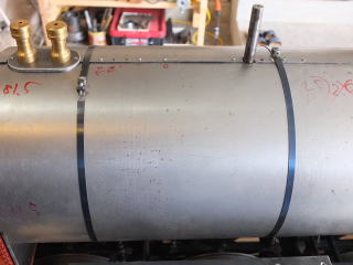
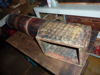
Dec. 2017
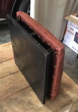
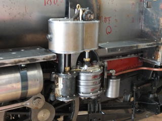
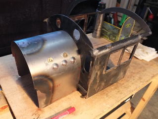
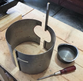
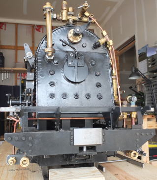
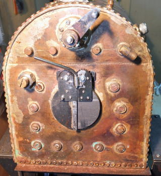
Boiler Cover
The cover on the boiler is completed. It is attached to the inside of
cab front with M2 screws. I made some accesaries on the cover.
Quenched ribbon steels bought in Japan bound the boiler covers. It looks better.
5,202
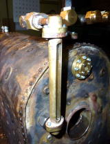
9
Oct. 2017
Cab
The front plate of the cab is t3 thick and the side plats are t2. As I
cannot round t2 thickness near roof, it was used a pipe of 44mm diameter
cut 60 degrees. It looks good. Main parts were soldered with silver. The
roof is not made yet.
5,157
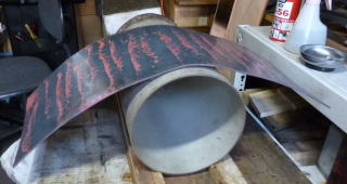
25
Apr. 2017
Boiler cover
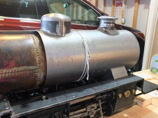
Steam Dome
The boiler is covered by the left and right rounded sheets of t1
thick. They are separated three parts in the longitudial direction. They
have flat bars on the top of boiler to fix the sheets by screw.
The steam dome has two parts. The upper part was shaved from a round
bar and the lower part was hammered from a round sheet.
Some sheets cover holes above the cylinders in the smoke box. Removable
inner stack is attached from outside.
4,970
26
Mar 2017
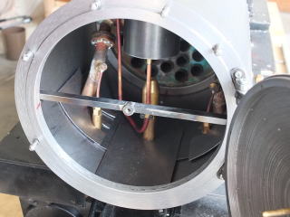
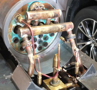
Draft Pipes
Draft steam pipe goes from steam distributer & draft valve to
under of smokestack though the reinforcing pipe of boiler.
Compressed air for draft is taken from a coupler (lower left side
of the boiler) and connected to draft pipe via below and right side of
boiler.
4,951
14
Mar 2017
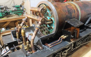
Oil Pipes
Pipes from oil pump(right side on the picture) to main steam pipes
through under body. There are check valves before main steam paipes.
4,938
25
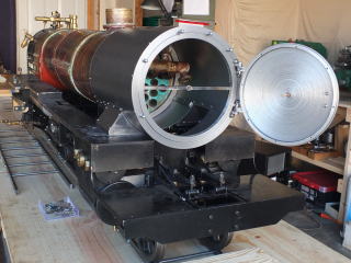
Feb 2017
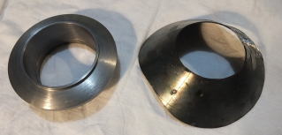
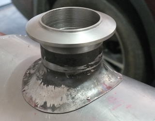
Smokestack
The face of the engine has been appeared. The ring is attached to the
tip of the boiler. The smoke box can be separated in order to remove easily.
The Smokestack was made from three parts. The upper was shaped from
disk, the middle was bent from sheet, and the lower was hammered from conical
sheet. It is my first try to hammered metal. I failed to make from cylinder
plate at first. Next I tried to hammer conical plate. It was succeed very
much.
Right side is the conical plate before hammerd.
4,928
5
Feb 2017
Smoke Box
The face of the engine has been appeared. The ring is attached to
the tip of the boiler. The smoke box can be separated in order to remove
easily.
4,890
2
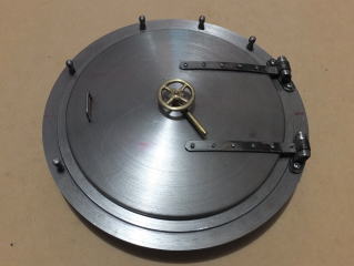
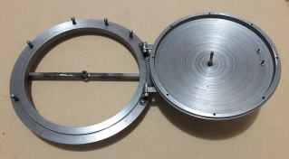
Jan 2017
Smoke Box Door
My work for the model has been begun from December at last. The
parts of the smoke box door were made in the U.S. They were shaped from
steel disks of φ215 & φ180.
December of Indiana was unusual cold I recognized -18℃. It is too cold to work. The
electric heater I prepared is almost useless for the wide garage. I endure
the cold during working.
4,842
6
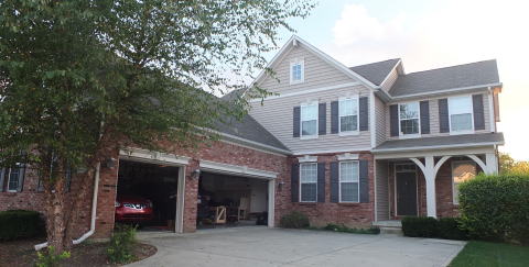
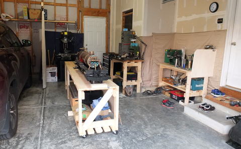
Oct 2016
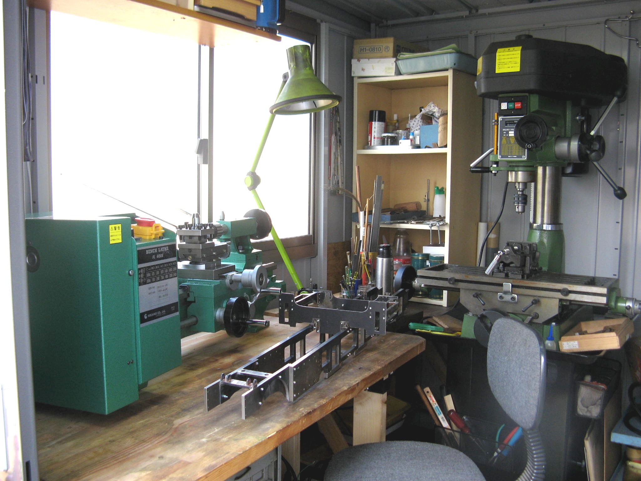
New house & Work shop
I spent at hotel for one month and moved to a rental house. It has
three garages that are two for cars and one for my work shop. The model
got no visual damage, but some bolts were loose.
Fishers, IN
My new work shop. All desks were made by 2x4.
4,769
31 July 2016
Luggage to the U.S.
Luggage was moved out two days before I depart to the U.S. I bring
the models, machines and tools without desks, shelfs, air compressor, compound
milter saw, LPG tank, sulfuric asid etc. After the luggage moving
4,769
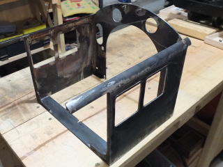
12 June 2016
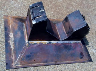
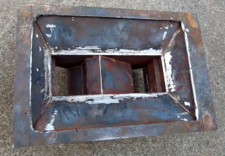
Cage for transport
An appointed notification to the U.S. has come to me suddenly.
I did not expect it at all.
I was hurried to prepare for transpotation of the model. I began to make
the cage for the model at first. It was made by steel angles with nuts
and bolts. After it was completed, I failed to put the model into the cage.
The model fell to the ground floor from the desk. I felt a big fear. However
the damage of the model was not big, becuse the front parts played the
role of bumper. Damage of the front parts
The front parts was repaired, and the model put into the cage.
4,724
14 May 2016
Tender/Painting
Tender has been completed by painting. It took about one yesr, 321
hours without plannig.
They were sanded before painting. The frames are painted to red.
Tender with a lever for a water pump, a lever for break, lebers for feet.
4,693
24
Apr. 2016
Outside plate of Tender
I moved to the head office in Tokyo from Kimitsu works where I have
been for two years. I go to new office by highway bus via aqualine. It
takes one and a half hours, but I need not to move my house.
The plates of the tender have been made for four months. The plates are
attached on the frames with screws. It was not used silver solder, because
heat deform the plates. Rebets on the plates are hit by my revet hammer
from back. My original revet hammer
21
Dec. 2015
Seprator
A separator is in a steam dome for seperating steam and water. Though
I did not know whether a separator of a model is useful, it was equipped.
4,549
19
Nov. 2015
Brake handle
The brakes of the driving wheels cannot stop the engine, but can
stop rolling. They are like parking brakes of automobiles. The braking
power reaches the brake shos of the wheels throug bars, levers and a spring
from the cab.
4,498
16
Sep. 2015
Tank frame of Tender
The tank frame of the tender are made of 9x9 6x9 flat bars which
were connected by M3 bolts. They are solid enough. Image of Driving
w
4,355
30
Aug. 2015
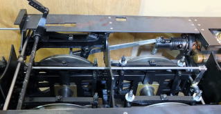
Brake System of Tender
The brake system of the tender is the same mechanism as the real
engines. I brake by the handle of the central right.
4,313
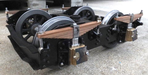
20
July 2015
Bogies of Tender
Nine years passed from tthe start.
The wheels, the axle boxes and the springs were assembles in the bogies of the tender.
4,221
7
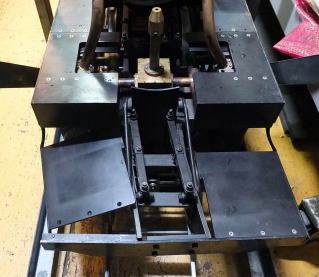
June 2015
Drain
The drain bars under the cylinders are operated by the cab through
rods and levers. Their movements are good.
4,160
7
June
2015
Painting
Whole of the frames were painted. All parts were taken to pieces
and painted. Before they were painting, they were pickled, or washed by
hot water. Any rust-preventing paint was not used. The kind of paints was
the emulsion of ASAHIPEN. It took about one month to assemble them.
4,160
5
Apr. 2015
Bogies of Tender
The bogies have a lot of prats of same forms. It took many hours
to make them. Such parts were pre-painted, and connected by 384 sets of
bolts and nuts. (M2.6 & M3)
These parts are 16 pieces to the two bogies.
4,045
28
Feb. 2014
Connector
It connects the engine and the tender. The buffer uses two coil
springs of φ2.5 wire, external φ15, heiht 22mm.
3,970
9
Nov. 2015
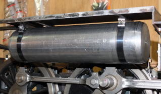
Air tanks
Air tanks were made of φ63.5mm pipes and suspended by steel ribbons.
3,864
28
Sep. 2014
Covers of cylinders
Covers of the cylinders were made from t1mm plates. The air valves
and the drain valves have the original function. The cylinder safety valves
and the eye holes are dummy.
Air valve Cylinder safety valve
Covers of the cylinder On the cylinder block
3,818
30
July 2014
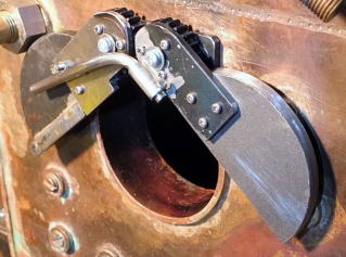
Fire doors
For the opening and shutting the fire doors, the gears are used.
3,763
26
June 2014
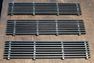
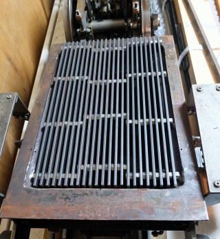
Fire grate
Fire grates were made from t3x13mm flat bars and M5 bolts. They
were divided into three parts to diposit and withdraw them from the fire
hole of the boiler.
3,723
16
May. 2014
Transeferd and Moved
I was transeferd to kimitsu(Chiba) from Kamaishi(Iwate). I looked for
a house with the space for my workshop, and I moved to the new house. My
workshop was dismantled and carryed by the truck. It was very hard work.
3,712
24
Jan. 2014
Running boards
The running boards were made from t3mm plates with the hemming of
t2x8mm flat bars. The checkered plates made by eching will be on them.
3,651
19
Jan. 2014
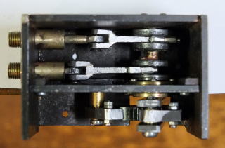
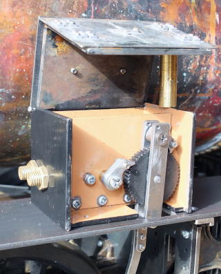
Oil pump
The mechanical pumps are moved from the valve gear. The ratchet
gear was bought. It was hard to make 29 small parts. I tried to express
details of the box surface. Plan view
2,882
9
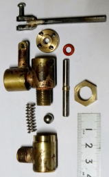
Nov. 2013
Whistle valve
Draft valve
2,882
21
Sep. 2013
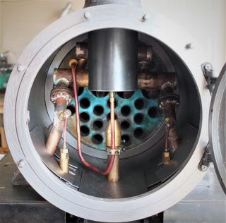
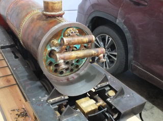
Boiler connection
The boiler was put on the frames. The regulator, the pressure gauge
and water gauge were installed to it. It connected to the cylinders with
the tubes. The pressure air into the boiler moves well the cylinders and
wheels through the regulator.
Safety valve
2,882
2nd
Sep. 2013
Superheater
They are four tubes in four large boiler tubes.
2,882
1st
Sep. 2013
Regulator valve
It is slide type.
2,882
10
Aug. 2013
Ashpan hooper
Opening of the covers is hand-operated (not remote from the cab)
and shutting is moved by the springs.
2,882
14
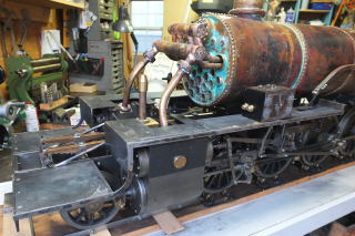
July 2013
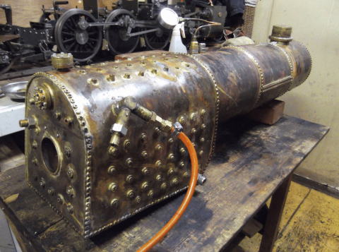
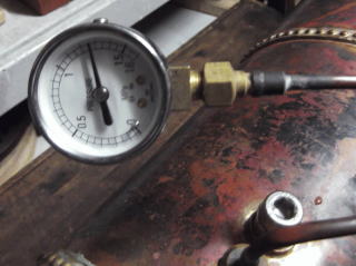
Completion of the third boiler
The third boiler was compeleted at last !
It took three years since I began to make the first one.
I could not clear the low pressured air test by repairing with silver solder. After I tried several times. I changed it to soft solder of hidf temperature melting point. It was very useful. At last, the boiler was tested by high pressured water and cleared more than 0.9MPa.
I improved following points mainly.
1) Copper was changed to oxygan-free.
2) Rivets and bolts pitch was shortened to 8mm
3) Copper plating bolts(M3) were used.
2,882
15
Apr. 2013
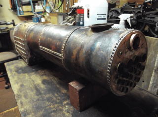
Third Boiler
The third boiler was made for nine month. The water in boiler leaked
from about 20 points. It is much better than the former failed boilers.
2,882
19
Aug. 2012
Boiler(remade)
I tried repairing the boiler again and again with acetylene burner.
But they were not success. At last , the reinforcing bars in boiler were
bending much. I gave up repairing the boiler. I think that the temperature
of acetylene burner is too high for silver solder.
I was shocked very much. I do not have any idea how to improve it.
2,882
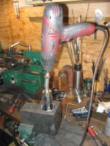
6
May. 2012
Boiler
(remade)
Water Guage
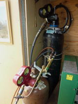
The remade boiler is not completed yet. Though I repeatedly re-solder
the place where air leaks, leaks of air do not decrease.
I try to use acetylene burner instead of liquefied petroleum gas(LPG). Because flame of acetylene burner is strong and thin, it is suitable
to re-solder small place only.
I made the water gauge, while I repaired the boiler.
Acetylene Burner Water Gauge
2,882
10
Mar. 2012
Boiler(remade)
The form of the remade boiler was finished. I begin to test by air
instead of water.
2,810
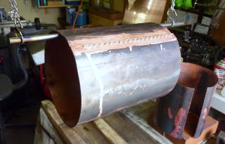
12
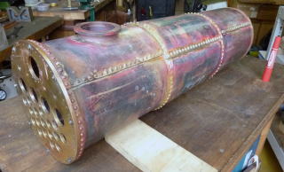
Oct. 2011
Boiler(remade)
The boiler body were made from 3 piece of pipes. I bent the 3mm
thickness copper plates by hand and made the pipes. The plates were
joined with rivets of 10mm pitch and soldered with silver.
2,583
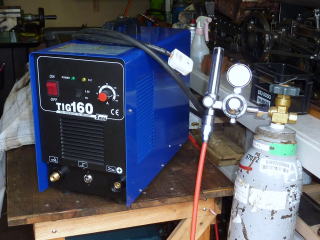
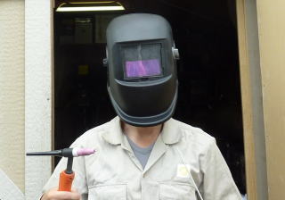
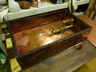
20 Aug. 2011
Water compartment(tank) and Handy pump
I tried welding with tungsten inert gas to make a water tank. The
result was not good. It is not better than solder for me.
2,489
11 June 2011
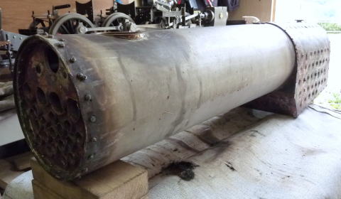
Boiler
The pipe of body was made by stainless steel, because of strength.
But it was too difficult for me to solder stainless steel and copper with
silver. This boiler was failure. It cannot keep water of the inside.I decided
to remake it.
The failure boiler
2,327
18 Mar. 2011
Tsunami
My town Kamaishi suffered great damage by the tsunami in 11th march
2011. All of my family were safe. I must work to save our co-workers and
restore our workplace for several months.
18 Oct. 2010
Guide pipe of Cylinder bar
These are just decorations in a dummy.
2,033
12 Sep. 2010
Reversing Gear
It is a rotary type of reversing gear.
1,983
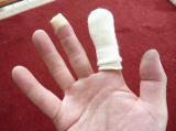
13 Aug. 2010
Running performance
Bravo! It is good performance to run at test of air. I feel that
it was good decision for me to use piston valves and piston lings.
I am sometimes a little hurt at my fingers. I did a little big injury to go to hospital this time at last.
18 July 2010
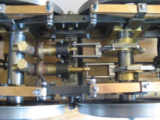
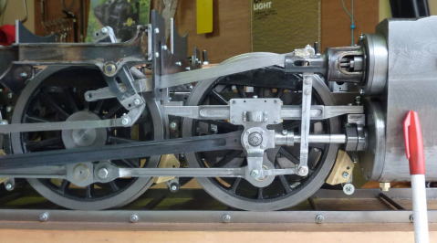
Valve Gears
It has finished to assemble the valve gears. They were revised to
make the traverse of No.1 driving wheels bigger. (The quantity of traverse
is +-5.5mm.)
1,884
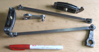
16 May 2010
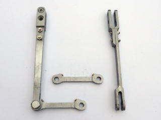
Links
Combinatiom links and Union links.
To the completion of valvegears, the remaining parts are slide bars, Cross
heads and valve bar's cross heads.
1,818
3 May. 2010
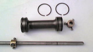
Cylinders
It has finished to assemble the cylinders. they are good performance
at test of air.
Piston Valve
1,788
2 Apr. 2010
Valve Bar Guide
They are dummys. My mind is easy for making dummy parts, even if
they are complex form.
1,753
14 Feb. 2010
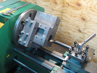
Cylinder Blocks
Cylimder Brock have almost finished making at last. It took 110
hours added 50 hours for the former mastaked ones. It was difficult to
process 12kg iron blocks(150x115x100mm). And it was more difficult to do
honning. Though honing is usually to ask an expert, I tried it. I do not
make sure about that result.
1,689
19 Dec. 2009
Return crank
Eccentric rod
Curved slotted link
While I have a hard fight for making cylinders, I made these parts.
They have brass bushing on rotation places.
1,583
13 Sep. 2009
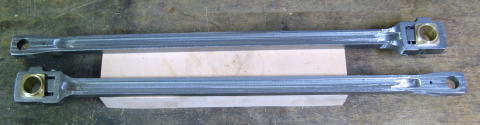
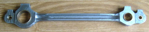
Main Rods
They have length of 400mm and thickness of 9mm.
They have bent easily after cutting the ditches with the millimg machine.
It was difficult to remake straight.
.
1,466
3 Aug. 2009
Coupling
Rods
It took many hours to make six coupling rods, but it were not very
dificult with my new milling machine. I tried seven times last time when
I made C58's one of gage 1.
1,428
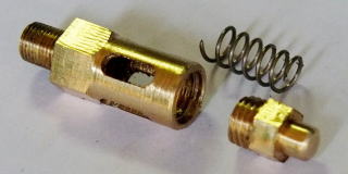
14 June 2009
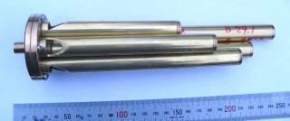
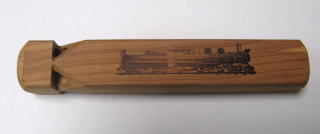
Whistle
The model of this whistle is the woodn whistle that I bought at
Durango railway museum in the U.S.
I am satisfied with the sound of five musical scales. It will be put in
the air tank. (four musical scales)
These pumps work in the thied driving wheels.
The sylinder bors are diameter of 8mm.
The piston strokes are 22mm.
1,357
16 May 2009
Break System
This break system moves four axes together. (Real engine moves by
tow axes.) This will work when the engine stop.
1,316
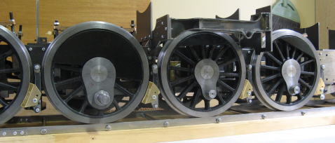
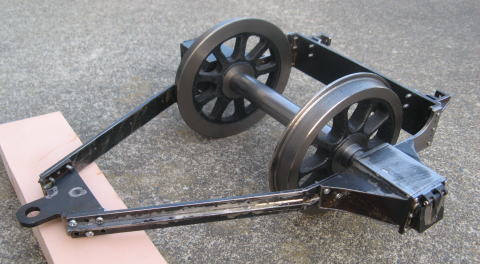
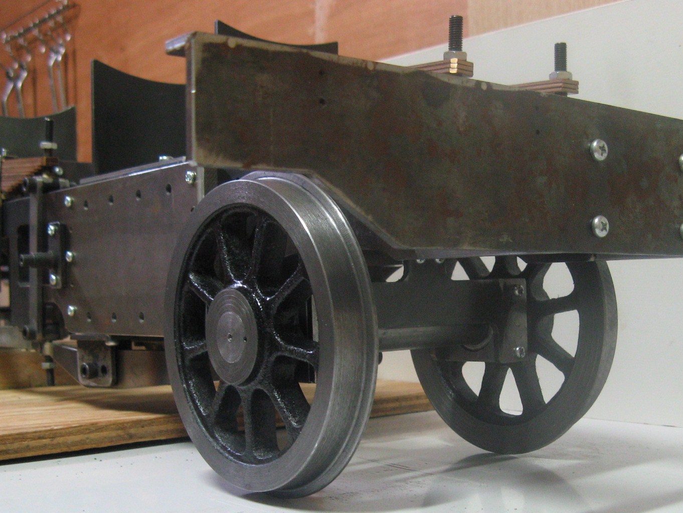
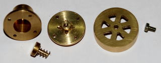
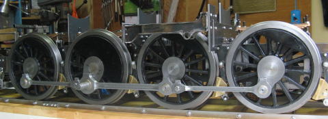
12 April 2009
Driving Wheels
It took 139 hours to make driving wheels from the castings.
Without counter weights
1,199
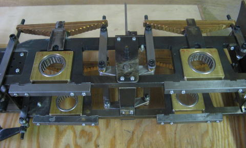
25 Jan. 2009
Bearing for Driving Wheels
Needle bearings were adopted.
1,097
18 Jan. 2009
Trailing Truck
The trailing truck was finished eight months later since I began
to make it last June before I moved.
1066
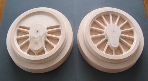
6 Dec. 2008
Wooden Forms of Driving Wheels
I had to remake them after I found a mistake of the driving wheel’s design.
984
14 Nov. 2008
Pilot Wheels
I had a hard
time to cut the wheels with the lathe.Cutting surface was very course, because I made a mistake in setting of
rotary speed of the new machine.
955
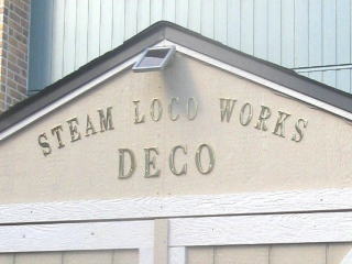
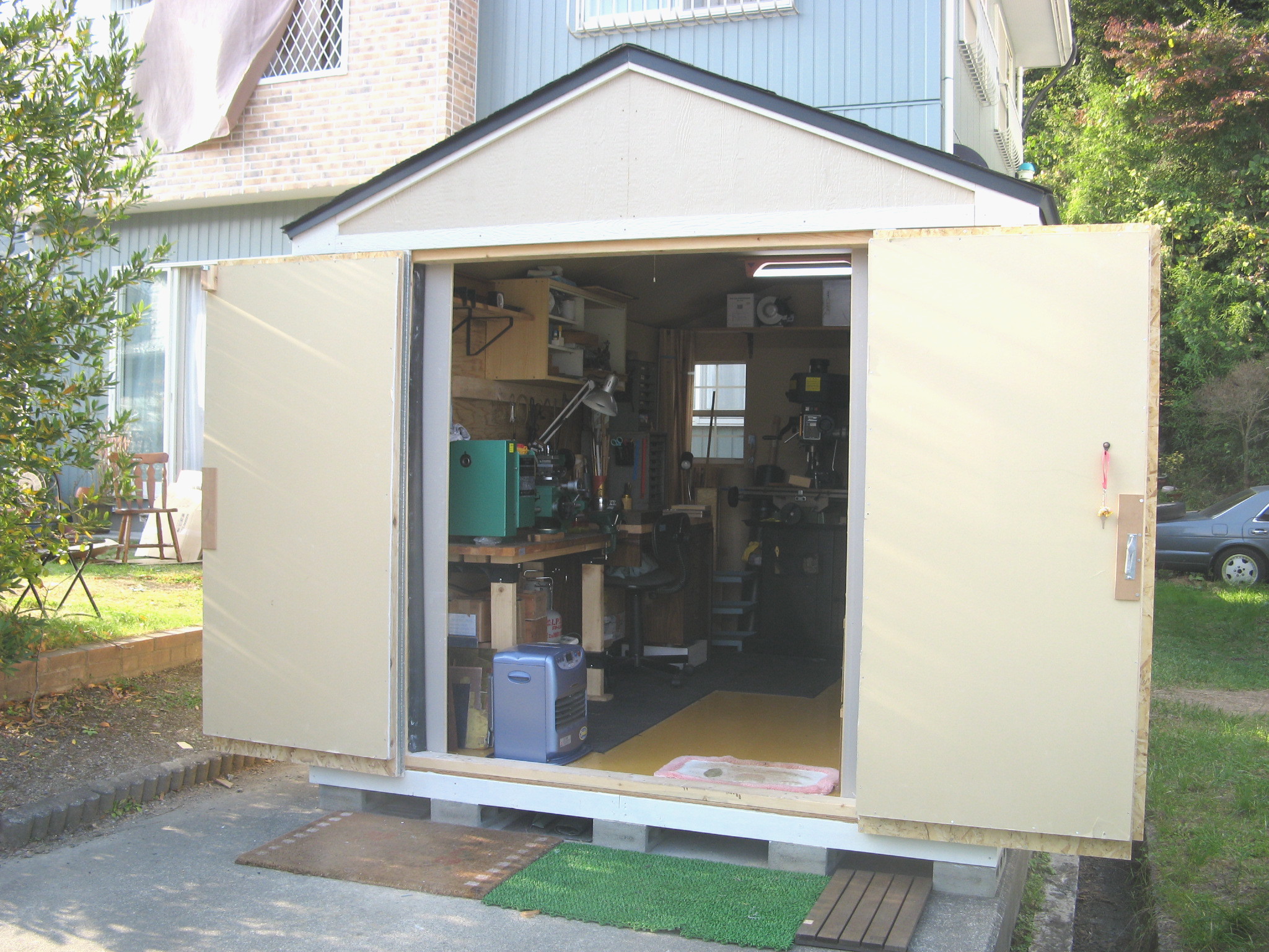
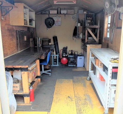
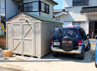
19 Oct. 2008
A New Workshop
My family
moved to Kamaishi.We live together again.I built a new
workshop on the garden of our new house.It was a kit made in the U.S.A.I added thick inner walls to the shed for soundproofing. The new shed was named “DECO”. D50 was called “Deco-maru” in Japanese.
926
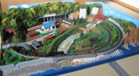
4 Oct. 2008
N Gauge
Making the scenery of N gauge layout was completed with a little more
in my dormitory.
It was completed in 31 Dec. 2008.
902
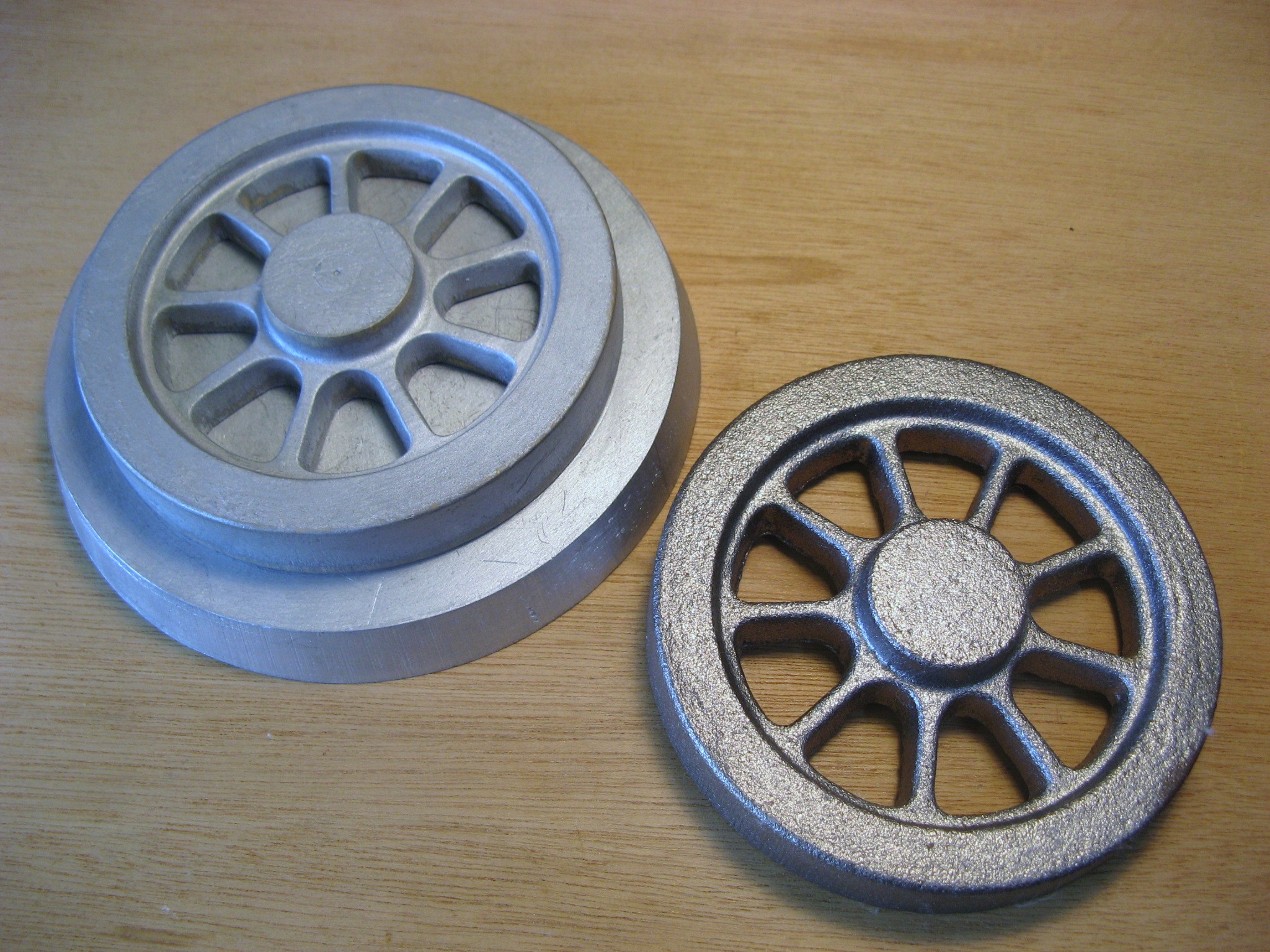
25 Sep. 2008
Pilot & TrailingWheels
Casting of the pilot and trailing wheels was finished in Tanaka industry
co. The castings are good. Especially their skin looks fine.
883
3 July 2008
Transefered
I have been transferred to Kamaishi works of Nippon Steel. I have
to live alone for a while at my company’s dormitory without my family.
While I cannot make the model of D50, I will make up
the scenery of N gauge layout.
835
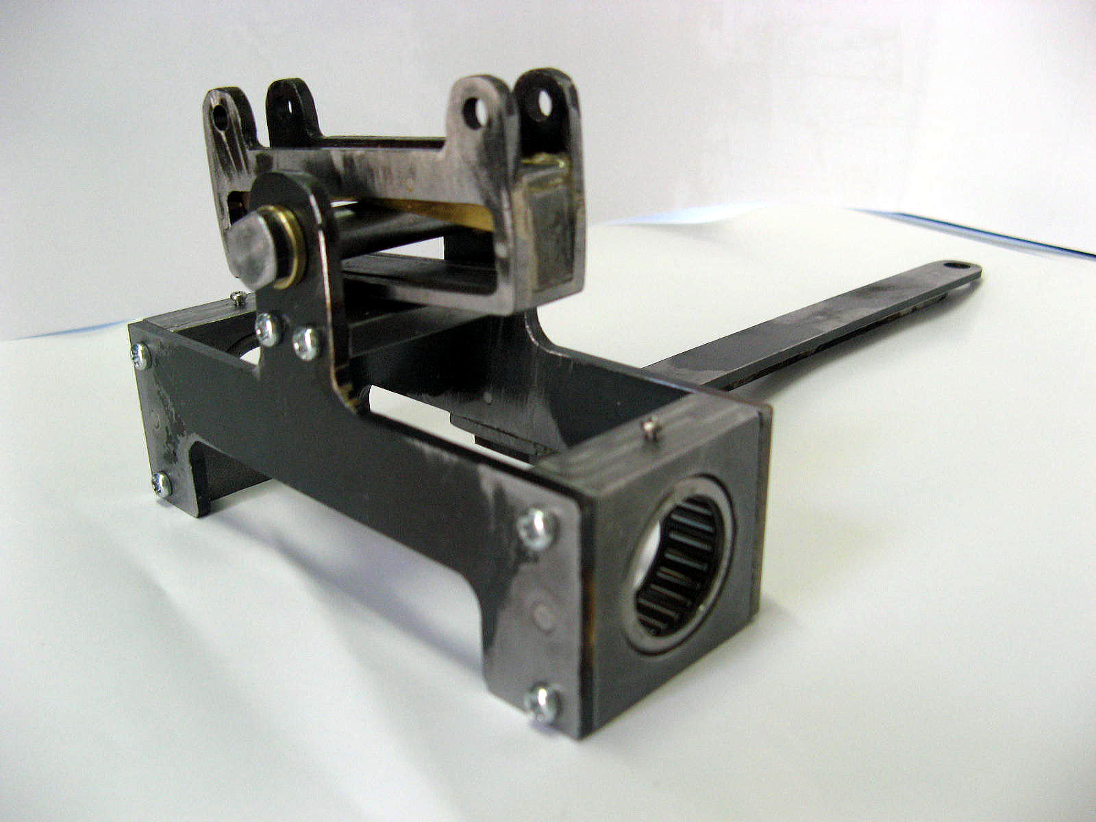
14 Jun. 2008
Pirot Truck
These are the pilot truck with the needle bearings and the side control.
The design of side control was modified by me in order to curve more than
the real.
809
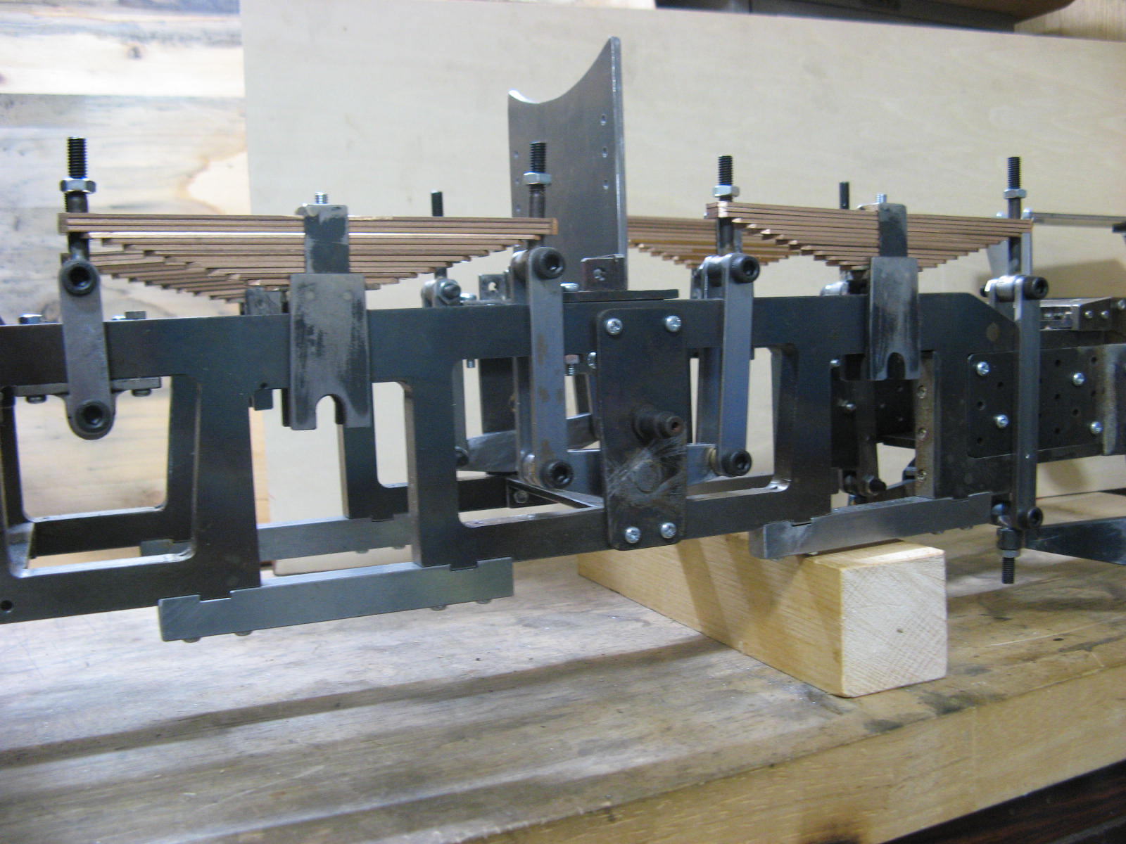
28 May 2008
Suspensions
I have used whole May to make the suspension system. There are lots of elements in them, such as 144 leaf springs, 64 links, 8 saddles and 8 equalizers and the other parts.
780
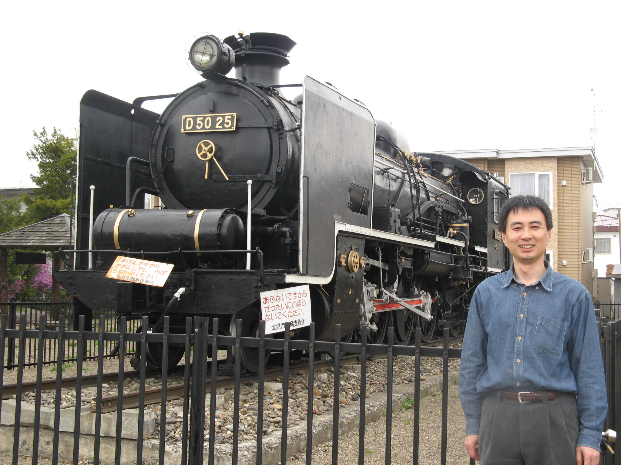
29 Apr. 2008
The other D50
There are only two D50 engine in Japan. One is No.140 in Umekouji museum
in Kyoto. I have been there. And I went to Kitami city of Hokkaido to meet
the other D50 (No.25) at last.
716
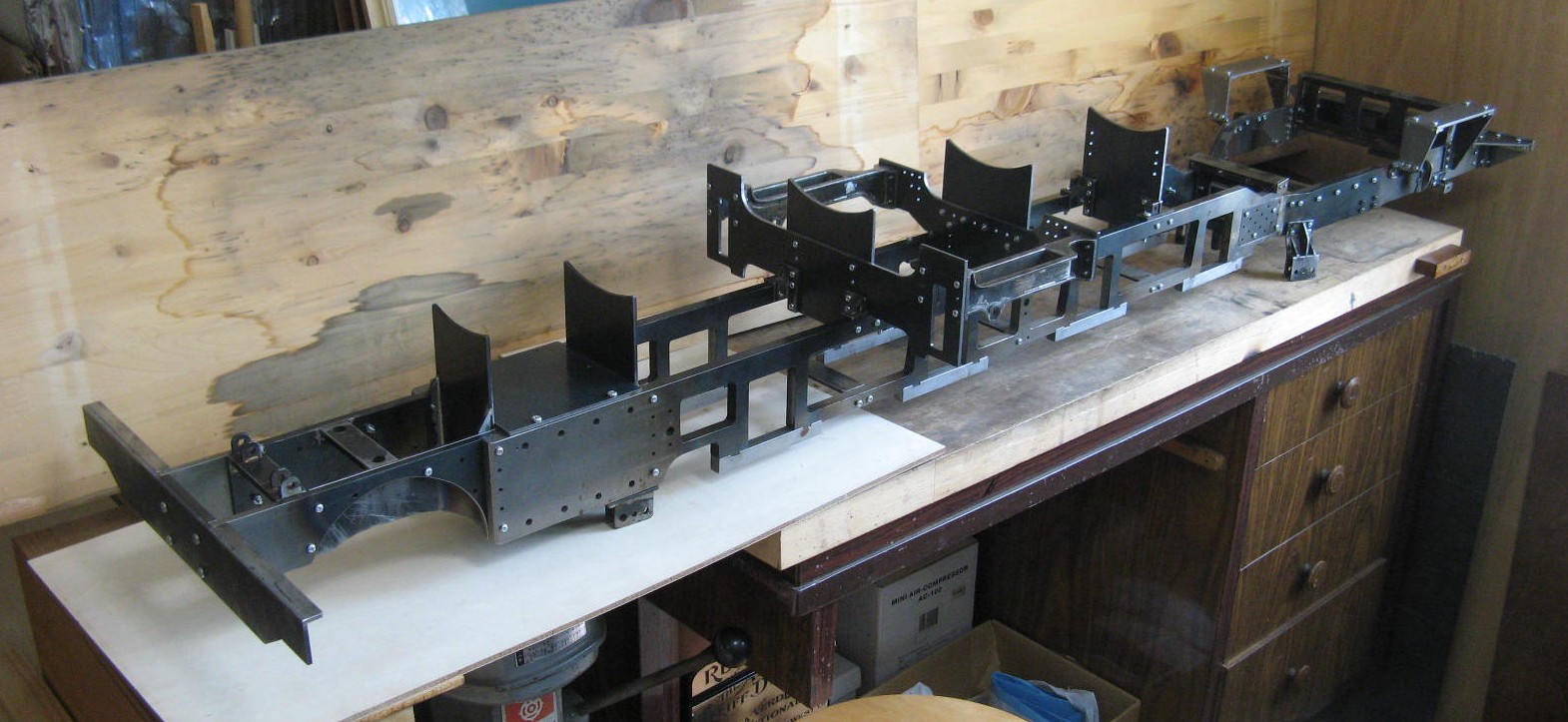
20 Apr, 2008
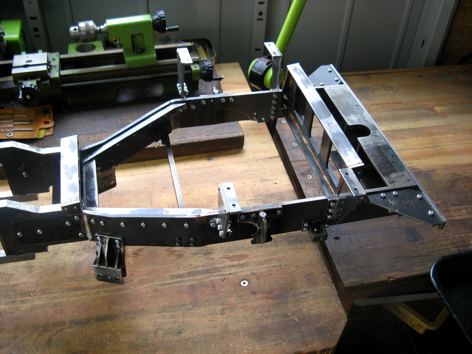
Under-Frames
The under -frames have been almost finished. they are bigger than I expected.
I have realized the size of 5 inch model.
There are only two D50 engines in Japan, now.One is No.140 in Umekoji of Kyoto.I have been
there.And I went to Kitami city of Hokkaido to meet the other D50 (No.25) at last.
702
5 Apr. 2008
New Lathe
A long-awaited lathe came at last! It is able to shape the driving
wheels of φ175. It is 100kg in weight.
Under-frames have been almost finished. They are bigger than I expected.
I have realized the size of the 5inch model.
664
23 Mar. 2008
Rear Frame
The rear frames have been finished with no trouble. It was well to bend
t4.5mm plate with accuacy.
636
20 Jan. 2008
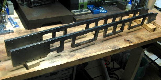
Main Frames
1.Deformation
The main frame bent after I cut t10 plates. I could not believe it.
I made straight them unwillingly with burner and long hours.
2.Mistake
Though I was very careful of cutting the main frames. I did make mistake.
I cut 48mm width against the correct 45mm width. It was repaired
by t3 plate and bolt with Loctite.
Production time : 52 hours
501
8 Dec. 2007
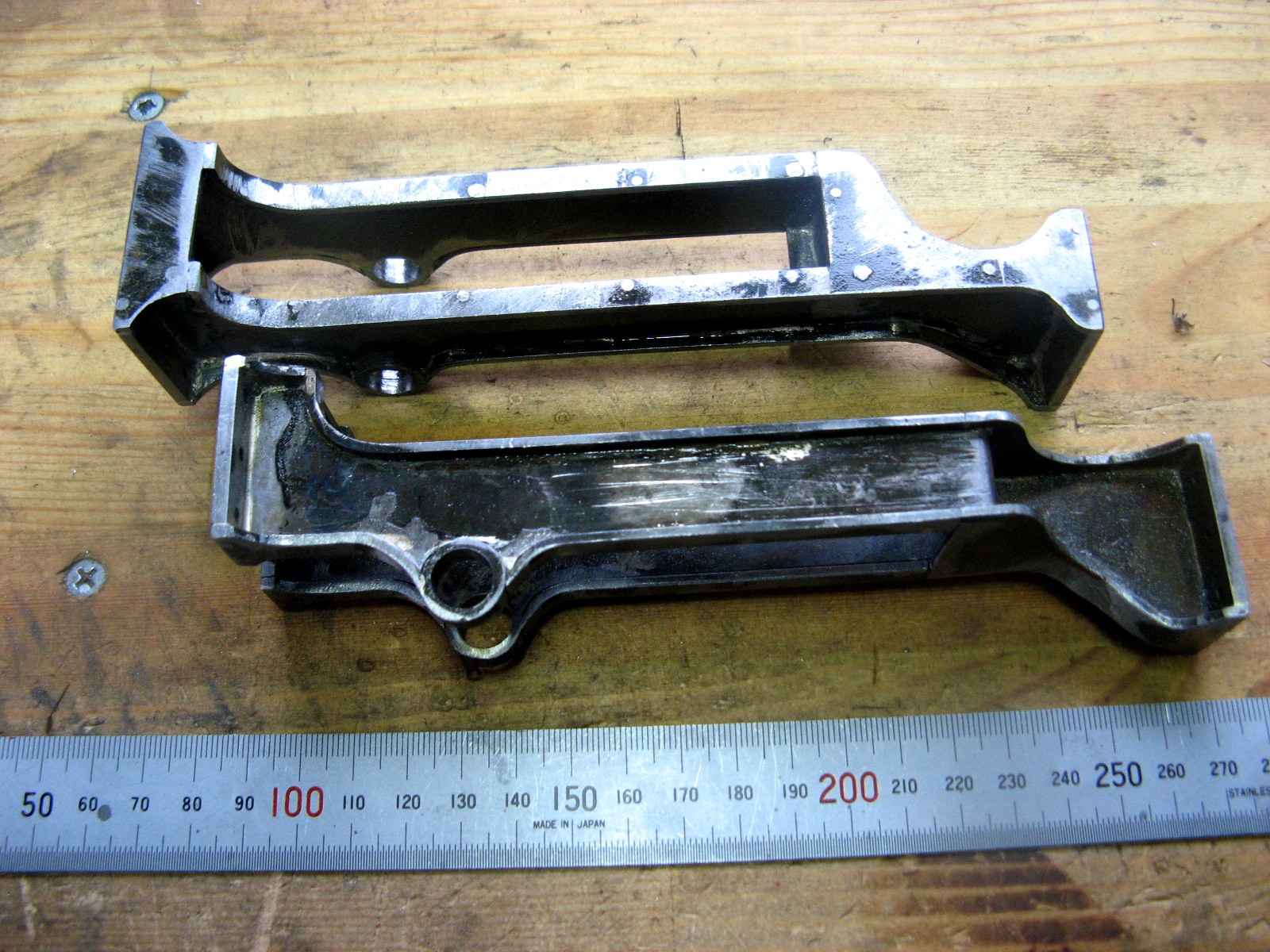
Motion Plates
It took 39 hours for the motion plates. I feel it was too long.
How many hours dose it take to finish the whole model? I have become
afraid of it.
I tried a new burner and silver solder. They are easy to use for
me.
430
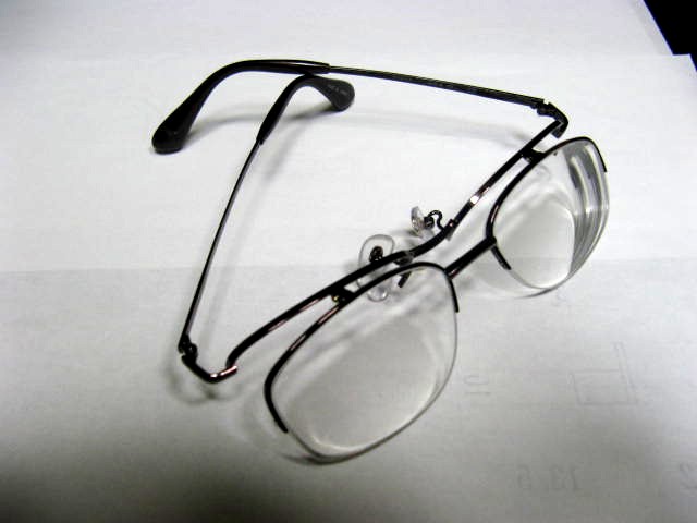
15 Sep. 2007
Convex Glasses
Because I have grown farsighted, I have often taken off my glasses.
So I prepared new up-down type of convex glasses to make the model.
I use my own eyes without the glasses when I see fine parts.My progressive nearsighted eyes are very
useful to see precision parts.
310
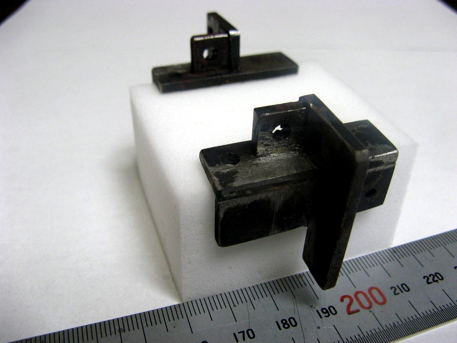
9 Sep. 2007
First Parts
I do not know the name of this part, this is one of the parts that connect
the main frames between 1st and 2nd wheels.
300
28 Aug. 2007
Bearing
Needle bearings will be used for all wheels. I judge that needle bearings
are better performance than metal bearins in real locomotive.
282
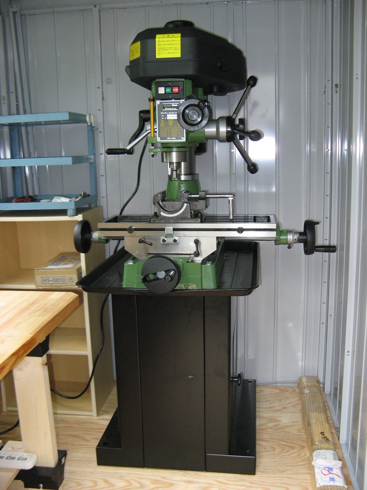
14 Aug. 2007
Short Break
My family (my wife, a daughter, two sons and I) traveled in U.S.
The milling machine was replaced. A new big machine was
made in Taiwan at 155kg in weight. I feel that machine tools are
much cheaper than 15 years ago, when I bought the mini-lathe.
It was very hard work for me to move the heavy machine from the front
door to the workshop.
277
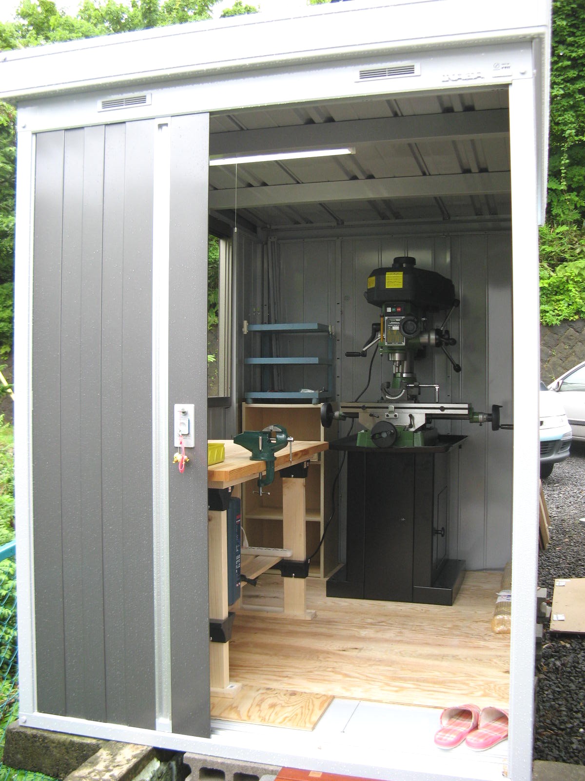
28 July 2007
Start of Product
I have started to make the model, as I was not able to endure only that
I designed.
My first workshop is a common storeroom of the steel. It is too small to complete 5inch engine. It is temporary workshop, because I may be transferred and move to another house. I will make parts of the engine in this small storeroom.
253
28 Apr. 2007
Observation Again
I visited Umekouji steam locomotive museum again to research the details
of D50.
209
15 Jan. 2007
Boiler
The boiler body will be made of stainless steel. The other part will be
copper.
135
22 Nov. 2006
Cylinder
The type of Double ports is adopted for the piston valve.
85
23 Sep. 2006
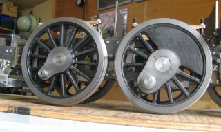
Wheels
I found that shapes of No.3 driving wheels and No.1,2,4 driving wheel are
differrent for the first time.
54
21 Sep. 2006
Observation
D50 140 is stored at steam locomotive museum 'Umekouji' in Kyoto which
is far from my town. I traveled there to observe it and took pictures.
34
18 Aug. 2006
Start of Design
I bought a CAD software of Photron. It is useful when I design on
the personal computer.
17
23 July 2006
Engine Model
I have chosen Japanese engine type of "D50". This type was
a first moderate engine made in Japan, which was designed in reference
to American type. Mikado type of wheels and stick under-frames were
adopted to D50 for the first time in Japan. 380 engine were made
from 1923 to 1931.
6
2 July 2006
Start
I prepare to make a live-steam engine of 5 inch gauge, which has been my
dream.
C58725 of 45 mm gauge engine was a training before I would make a 5 inch gauge engine. However it took 13 years to complete it. I have hesitated to make a next engine. May I really make it up? 5 inch gauge engine will be much bigger (about three times) than 45 mm gauge one.
One year passed after I finished making C58725. Now I
have decided that I begin to make it first of all.
 Lionel 262E
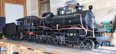
 After the luggage moving
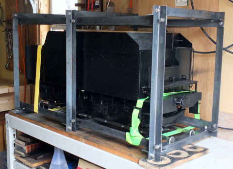
 Damage of the front parts
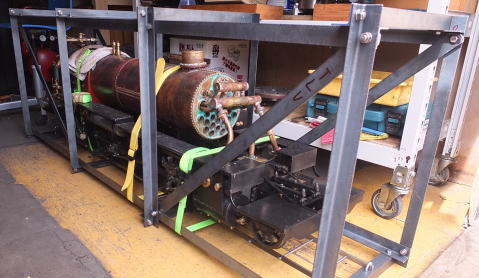
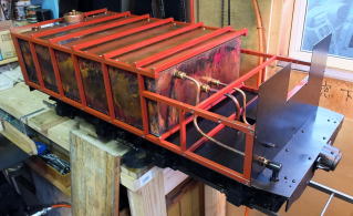
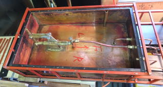
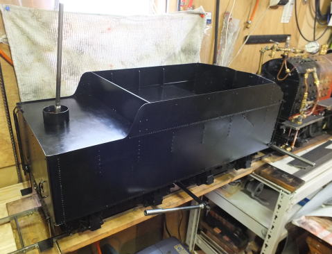
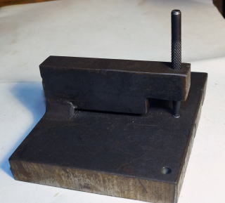
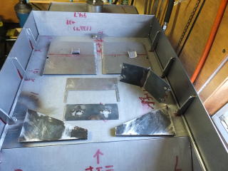
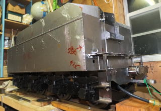
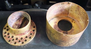
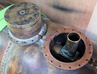
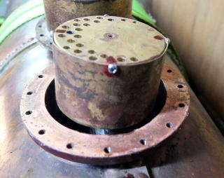
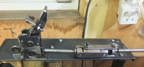
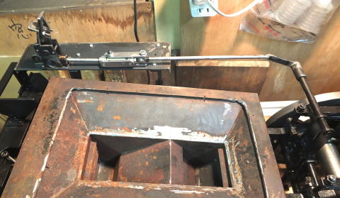
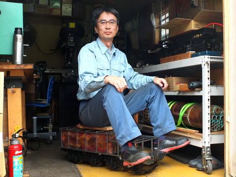 Image of Driving
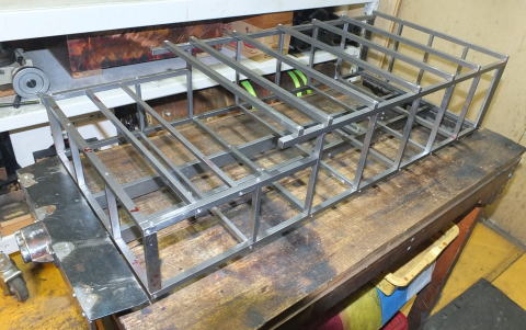 w
w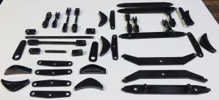

 Plan view
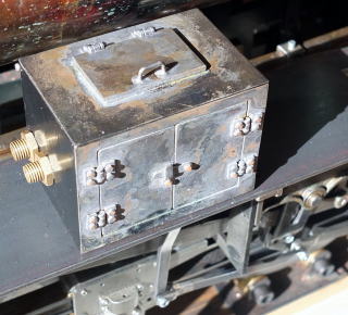
 Safety valve
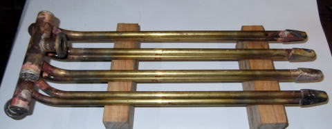
 Piston Valve
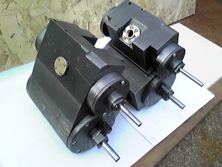
 (four musical scales)